ESP32-C3-DevKitM-1 is an entry-level development board based on ESP32-C3-MINI-1, a module named like this due to its small size. This board provides a full range of Wi-Fi and Bluetooth LE functions. It is expected to hit the stores in the second half of April 2021.
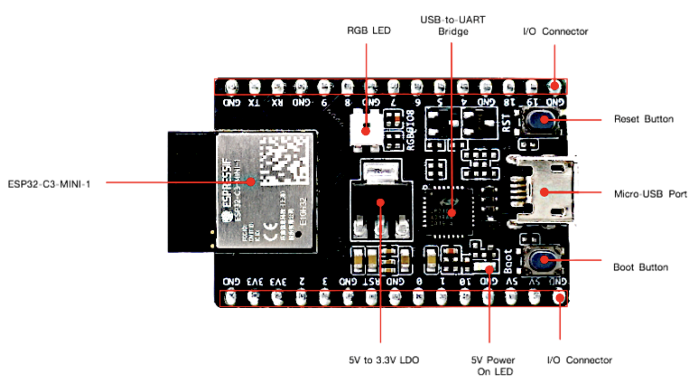
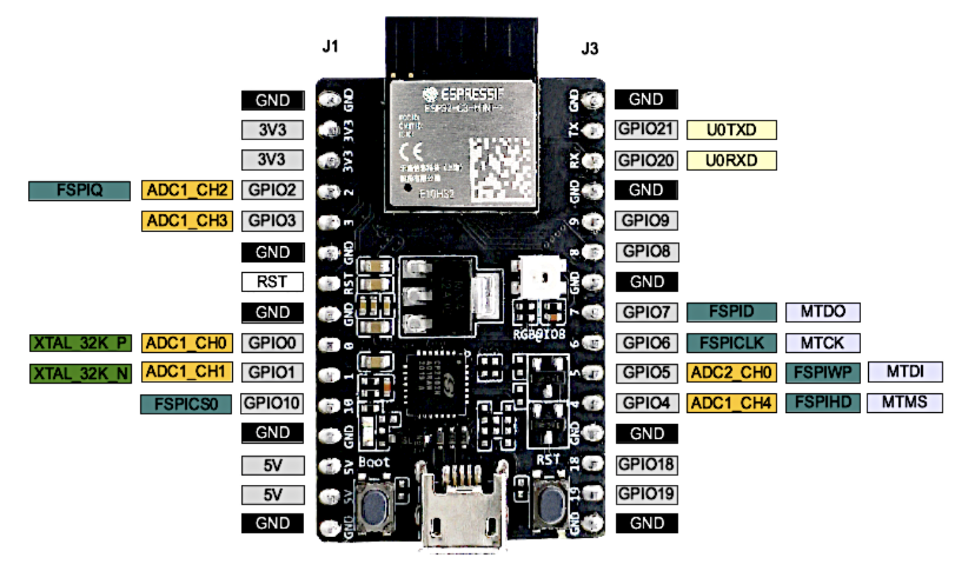
Most of the I/O pins on the ESP32-C3-MINI-1 module are broken out to the pin headers on both sides of this board for easy interfacing. Developers can either connect peripherals with jumper wires or mount ESP32-C3-DevKitM-1 on a breadboard.

One of the key components is ESP32-C3-MINI-1, which is a general-purpose Wi-Fi-and-Bluetooth-LE combo module that comes with a PCB antenna. At the core of this module is ESP32-C3FN4, a chip that has an embedded flash of 4 MB. Since flash is packaged in the ESP32-C3FN4 chip, rather than integrated into the module, ESP32-C3-MINI-1 has a smaller package size.
There is a power regulator that converts a 5 V supply into a 3.3 V output, turning on when the USB power is connected to the board. All available GPIO pins (apart from the SPI bus for flash) are broken out to the pin headers on the board. (For more details, please see the Header Block.)
The Micro-USB Port can be used as a USB interface, a power supply for the board, or a communication interface between a computer and the ESP32-C3FN4 chip. By pressing the Reset button, the system gets restarted, while the USB-to-UART Bridge provides transfer rates of up to 3 Mbps. Last, but not least, there is an addressable RGB LED (WS2812), driven through GPIO8.
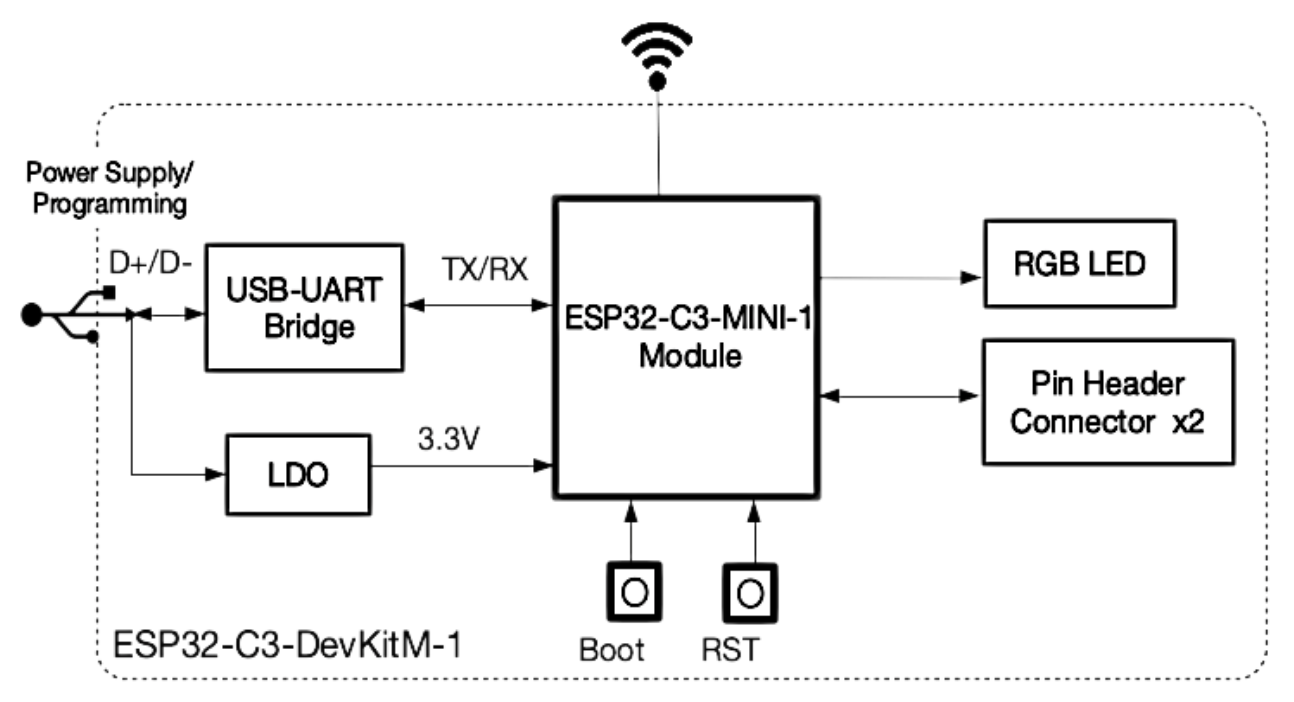
The block diagram below shows the components of ESP32-C3-DevKitM-1, and their interconnections.

There are three mutually exclusive ways to provide power to the board:
It is recommended that you use the default option, namely, the micro USB port.

MCU
WiFi
Bluetooth®
Hardware
Test
The board can currently be programmed with the ESP-IDF framework, and all the necessary instructions for developers to get started can be found here.