 HT32F616xx Battery Monitoring MCUs : Battery-powered devices of all kinds have become indispensable in today’s households. From gardening tools such as lawnmowers to tools like cordless screwdrivers or even vacuum cleaners, which would not be possible as robots without batteries.
The battery must be monitored during charging and discharging so as to ensure it is not operated beyond its voltage and current limits and does not overheat. This would not only damage the battery and shorten its service life, but in the worst case it could cause the battery to explode.
Many battery-powered devices use batteries with 3 or more battery cells in series. Even if the individual cells initially have almost identical properties, sooner or later there will be deviations due to the charging and discharging cycles, ageing processes and other factors. The performance of a battery pack is determined by the weakest cell. This cell is charged and discharged the fastest. Without further measures, the other cells can no longer reach their maximum state of charge. Thus, the battery pack is used inefficiently and can no longer call up its full power. The solution is known as cell balancing, which can be realised with different methods (passive and active). Passive and active balancing allow each cell to be charged to its maximum state of charge. Active balancing, which also considers the state of discharge, is the more efficient but also more costly method.
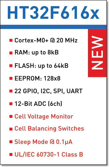
The new Cortex-M0+ HT32F616xx Battery Monitoring MCUs from Holtek offer, for instance, integrated voltage monitoring and passive cell balancing for 3-8 lithium ion cells.
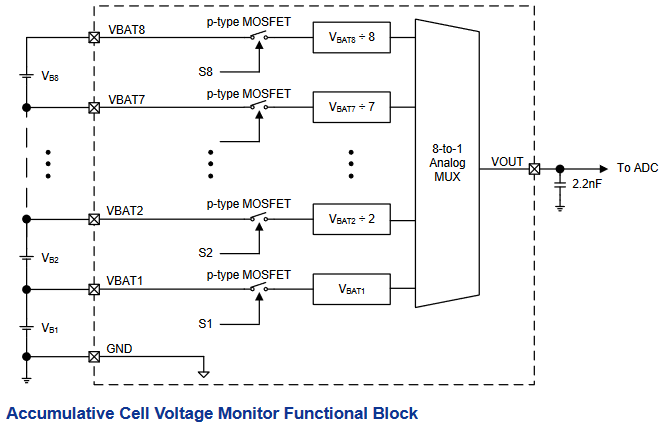
The cell voltage monitor consists of one P-channel MOSFET and one voltage divider per cell connection together with an 8 to 1 multiplexer. It has 4 control bits that switch the P-channel MOSFETs. The control bits are set via the I2C interface dedicated to the voltage monitor. The cell voltage is measured accumulatively and divided by the number of cells at the voltage output VOUT. These values therefore do not directly correspond to the actual voltage values of the individual cells (apart from cell 1), because only the average value over the stack of cells can be determined.
Usually, all cell voltages of the stack are determined in one scan. Holtek recommends scan frequencies below 100Hz (single cell measurement). It is important to allow a minimum wait time of 5 milliseconds to ensure that the capacitor at VOUT is fully charged. With the average cell voltages determined in this way, the true voltages can be determined by using a simple recursive back-calculation. For more details on this, it is worth looking at application note AN0543 for the HT45F8xxx series, which also has a cell voltage monitor that uses the same method.
The voltage monitoring unit also contains drivers for switching the charge and discharge MOSFETs. With the two drivers for discharging, two separate discharge paths can be realised.
FETs and resistors for passive cell balancing are also integrated. This means that only one series resistor is required as an external circuit to set the balancing current. Holtek is working on a reference code for the implementation of the balancing functions. This is expected to be available by the end of July.
Holtek provides a dedicated UL/IEC 60730-1 Class B Safety Test Library for their HT32 (Arm Cortex-M) MCUs, which customers can integrate into their own project or firmware. This significantly reduces the development time for Class B compliant devices.
The user guide to the safety test library can be found on this page.
Further information on the development of IEC 60730 Class B compliant MCU applications can be found in this document.
You need more information? Our team will be happy to advise you on the cellular solutions from Holtek